Note: This product has reached end of production. Please use the recommended replacement.
Please click the [Remaining Inventory] button to see inventory available.
The recommended replacement is:
MFG Part Number: 1515.01
Description: WL1500
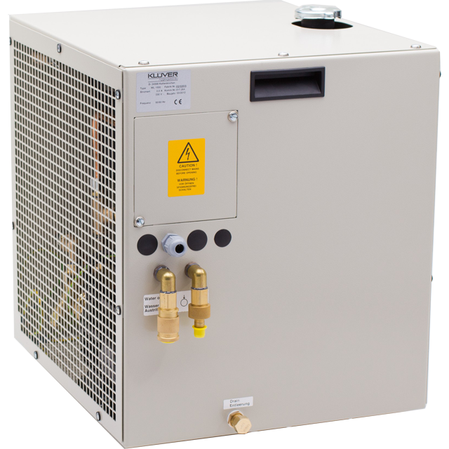
The WL1500 is a re-circulating liquid to air heat exchanger that offers dependable, compact performance by removing large amounts of heat from a liquid circuit. The coolant is re-circulated using a high pressure pump to assure maximum flow rate. Heat from coolant is absorbed by a radiant heat exchanger and dissipated into the ambient environment using brand name fan. Manual adjustments can be made to control flow switch. Customized features are available, however, MOQ applies.
- Cooling to ambient
- High heat pumping capacity
- Compact form factor
- Long life operation


Fluid Operating Points
Cooling Power (Qc) = Watts
Thermal Conductance = W/°C
ΔT (Ambient-Coolant)* = °C
ΔT (Outlet-Inlet)** @ 6.0 L/min = °C
Cooling Power (Qc) = Watts
Thermal Conductance = W/°C
ΔT (Ambient-Coolant)* = °C
ΔT (Outlet-Inlet)** @ 6.0 L/min = °C
Cooling Power (Qc) = Watts
Thermal Conductance = W/°C
ΔT (Ambient-Coolant)* = °C
ΔT (Outlet-Inlet)** @ 6.0 L/min = °C
Cooling Power (Qc) = Watts
Thermal Conductance = W/°C
ΔT (Ambient-Coolant)* = °C
ΔT (Outlet-Inlet)** @ 6.0 L/min = °C
Select Graph
* ΔT (Ambient-Coolant) is the temperature difference between the ambient temperature and the coolant temperature that is at the outlet of the heat exchanger during steady-state operation. This temperature difference would initially be 0 and increase to the steady state value under load. This would also be the temperature at the inlet to the application.
** ΔT (Outlet-Inlet) is the temperature difference between the inlet temperature and the outlet temperature of the application at the nominal coolant flow. More flow (application pressure drop less than nominal) would necessarily mean a smaller ΔT.
- Check coolant level regularly. For optimal cooling performance, coolant level should always be above radiator fins.
- Hose selection should be of material and thickness to support pressure resistance and coolant type.
- Manual adjustments can be made to control pressure flow rate.
- Check air filter and coolant filter periodically for replacement.
- Multiple cord plug options available to accommodate regional socket outlet requirements. Consult with Laird Technologies on cord plug selection.
Any information furnished by Laird and its agents, whether in specifications, data sheets, product catalogues or otherwise,
is believed to be (but is not warranted as being) accurate and reliable, is provided for information only and does not form part of any contract with Laird.
All specifications are subject to change without notice. Laird assumes no responsibility and disclaims all liability for losses or damages resulting from use
of or reliance on this information. All Laird products are sold subject to the Laird Terms and Conditions of sale (including Laird’s limited warranty)
in effect from time to time, a copy of which will be furnished upon request.
© Copyright 2019-2025 Laird Thermal Systems, Inc. All rights reserved. Laird™, the Laird Ring Logo, and Laird Thermal Systems™ are trademarks or registered
trademarks of Laird Limited or its subsidiaries.
Revision: 00 Date: 06-01-2022
Print Date: 01-18-2025

