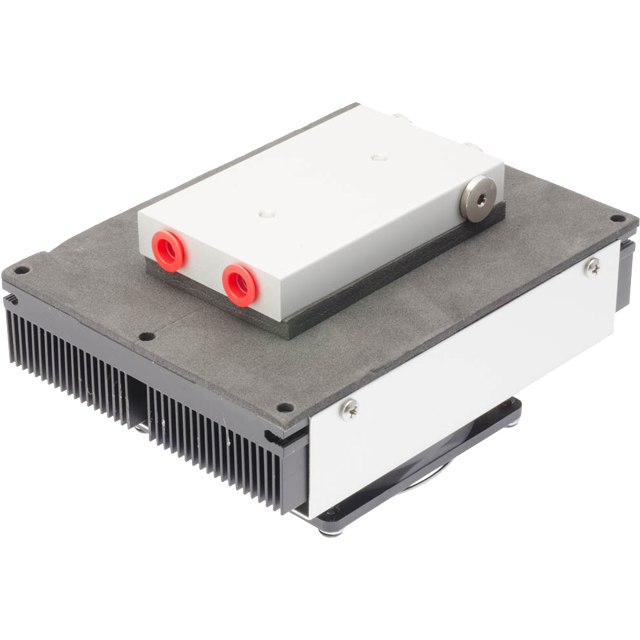
The LA-045-24-02 thermoelectric cooler assembly offers dependable, compact performance by cooling objects via liquid to transfer heat. Heat is absorbed through a liquid heat exchanger and dissipated thru a high density heat sink equipped with an air ducted shroud and brand name fan. The thermoelectric modules are custom designed to achieve a high coefficient of performance (COP) to minimize power consumption. It has a maximum Qc of 47 Watts when ΔT = 0 and a maximum ΔT of 42 °C at Qc = 0. The liquid heat exchanger is designed to accommodate distilled water with glycol. Corrosion resistant turbulators are enclosed inside channels to increase heat transfer. Mating port adaptors are sold separately.
- Compact design
- Precise temperature control
- Reliable solid-state operation
- DC operation
- RoHS-compliant
You can interact with the Performance Curves below to
estimate the cooling performance by entering the thermal and electrical operating conditions for your application.
Click the [Custom Datasheet] button to create a Customized PDF Datasheet.
Please Note: Actual application performance will vary from calculated values based on actual thermal design characteristics.
Use the sliders, input fields and [UPDATE] button below to enter your application's electrical and thermal conditions.
Use the Graph Y and X Axis buttons to display a variety of performance curves
and use the Voltage/Current slider to choose the electrical operating point to display performance.
Click [Custom Datasheet] button to save your results as a Customized PDF Datasheet.
Select Graph
Y - Axis
Select Graph
X - Axis
System Resistance
Cooling Power (Qc) = 10.68 Watts
TEM Voltage = 10.77 Volts
TEM Current = 1.00 Amps
TEM COP = 0.99
Power Supply = 10.8 Watts
Power Dissipated (Qh) = 21.44 Watts
Fan Voltage = 24.0 Volts
Fan Current = 0.4 Amps
Cooling Power (Qc) = 30.26 Watts
TEM Voltage = 30.13 Volts
TEM Current = 2.86 Amps
TEM COP = 0.35
Power Supply = 86.0 Watts
Power Dissipated (Qh) = 116.3 Watts
Fan Voltage = 24.0 Volts
Fan Current = 0.4 Amps
Any information furnished by Laird and its agents, whether in specifications, data sheets, product catalogues or otherwise,
is believed to be (but is not warranted as being) accurate and reliable, is provided for information only and does not form part of any contract with Laird.
All specifications are subject to change without notice. Laird assumes no responsibility and disclaims all liability for losses or damages resulting from use
of or reliance on this information. All Laird products are sold subject to the Laird Terms and Conditions of sale (including Laird’s limited warranty)
in effect from time to time, a copy of which will be furnished upon request.
© Copyright 2019-2025 Laird Thermal Systems, Inc. All rights reserved. Laird™, the Laird Ring Logo, and Laird Thermal Systems™ are trademarks or registered
trademarks of Laird Limited or its subsidiaries.
Revision: 00 Date: 06-01-2022
Print Date: 03-25-2025
Contact Sales

Sales and Support Centers
Asia/Pacific: +86 755 3698 8333 x218
Americas: +1 919-597-7300
EMEA (DE): +49 8031 6192887
EMEA (SE): +46 31 7046757
EMEA (CZ) +420 488 575 111
Contact Tech Support
Sales and Support Centers
Asia/Pacific: +86 755 3698 8333 x218
Americas: +1 919-597-7300
EMEA (DE): +49 8031 6192887
EMEA (SE): +46 31 7046757
EMEA (CZ) +420 488 575 111