The PCX4-6-F1-2040-TA-RT-W6 is a high-performance thermoelectric cooler designed for thermal cycling between multiple temperature set points and is ideal for applications in healthcare among others, where fast temperature changes are required. The thermoelectric module is specially constructed to reduce the amount of stress induced on the thermoelectric elements during operation. It has a maximum Qc of 16.8 Watts when ΔT = 0 and a maximum ΔT of 73.6 °C at Qc = 0.
- High thermal cycling capability
- Precise temperature control
- Solid-state operation
- Boosted performance with next-gen material
- RoHS-compliant
You can interact with the Performance Curves below to estimate the cooling performance
by entering the thermal and electrical operating conditions for your application.
Click the [Custom Datasheet] button to create a Customized PDF Datasheet.
Please Note: Actual application performance will vary from calculated values based on actual thermal design characteristics.
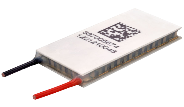
For maximum performance, be sure to orient the CONTROL side of the TEC against the application to be managed and the AMBIENT side against the heat sink or other heat rejection method. The CONTROL side is always opposite the side with lead attachments. Lead attachment is a passive heat loss and less impactful if located on the side that attaches to the heat exchanger.
Use the sliders, input fields and [UPDATE]
button below to enter your application's electrical and thermal conditions.
Use the Graph Y and X Axis buttons to display a variety of performance curves and use the
Voltage/Current slider to choose the electrical operating point to display performance.
Click the [Custom Datasheet] button to save your results as a Customized PDF Datasheet.
Select Graph
Y - Axis
Select Graph
X - Axis
Cooling Power (Qc) = 1.6 Watts
Current = 0.41 Amps
Voltage = 0.99 Volts
Power Supply = 0.4 Watts
COP (Qc/Pin) = 3.97
Power Dissipated (Qh) = 2 Watts
Cooling Power (Qc) = 15.05 Watts
Current = 4.33 Amps
Voltage = 8.04 Volts
Power Supply = 34.83 Watts
COP (Qc/Pin) = 0.43
Power Dissipated (Qh) = 49.89 Watts
0.165 ± 0.0010 in
0.001 in / 0.001 in
6.00 in
- Max operating temperature: 120°C
- Do not exceed Imax or Vmax when operating module
- Reference assembly guidelines for recommended installation
- Solder tinning also available on metallized ceramics
Any information furnished by Laird and its agents,
whether in specifications, data sheets, product catalogues or otherwise,
is believed to be (but is not warranted as being) accurate and reliable,
is provided for information only and does not form part of any contract with Laird.
All specifications are subject to change without notice.
Laird assumes no responsibility and disclaims all liability for losses or damages resulting from use
of or reliance on this information. All Laird products are sold subject to the Laird Terms and Conditions of sale
(including Laird’s limited warranty)
in effect from time to time, a copy of which will be furnished upon request.
© Copyright 2019-2025 Laird Thermal Systems, Inc.
All rights reserved. Laird™, the Laird Ring Logo, and Laird Thermal Systems™ are trademarks or registered
trademarks of Laird Limited or its subsidiaries.
Revision: 00 Date: 06-01-2022
Print Date: 03-11-2025
Contact Sales

Sales and Support Centers
Asia/Pacific: +86 755 3698 8333 x218
Americas: +1 919-597-7300
EMEA (DE): +49 8031 6192887
EMEA (SE): +46 31 7046757
EMEA (CZ) +420 488 575 111
Contact Tech Support
Sales and Support Centers
Asia/Pacific: +86 755 3698 8333 x218
Americas: +1 919-597-7300
EMEA (DE): +49 8031 6192887
EMEA (SE): +46 31 7046757
EMEA (CZ) +420 488 575 111