Introduction
Tier 1 OEM’s in telecom infrastructure market are designing the next standard for telecommunications, 5G. It will provide faster data transmission speeds than current LTE (4G) systems, approaching broadband speeds achieved with landlines. The latency will be much lower, reducing the number of times packets need to be resent. This will be great for mobile users in densely populated areas trying to stream movies, music or live TV on their smart devices.
Faster data communications will present challenges for critical components of telecommunication networks such as optical transceivers. Optical transceivers are installed in radio units to transmit and receive data from the base station. The temperature of the device in outdoor environment will increase due to smaller form factors and no access to forced airflow, which will increase the heat flux density of the radio unit. This results in high operating temperatures that exceed the maximum temperature limit of the optical transceiver, thus requiring an active cooling solution.
Optical Transceivers
An optical transceiver is a small form factor (SFP) pluggable transceiver, see image below. The transceiver contains a laser diode that converts data into light signals and vice versa, enabling high-speed data transmission at far distances. To assure transmission of data, temperatures should be kept typically below 70°C. The traditional thermal solution for the QSFP is currently passive, containing an interface material attached to a heat sink that dissipates heat through natural convection. This option, however, has been found to have difficulty with rejecting heat into ambient environment for radio units in 5G systems.
In natural convection, the heat transfer occurs from thermodynamic principal of heat moving from hot to cooler region to find equilibrium or in this case from transceiver to heat sink to ambient air. Large surface areas are required to convect heat naturally, and unfortunately SFP form factors cannot accommodate large heat sinks. In forced convection, the heat transfer is assisted by forced airflow from fans and the heat transfer will improve with velocity of airflow. However, fans are not permitted due to the high maintenance costs with replacing them in the field. Many radio units are located in towers and are not easily accessible. Outdoor environments can be harsh, which will limit the operating lifetime of a fan versus indoor applications. Therefore, it is not expected that such a thermal solution will be cost effective for cooling of optical transceivers in outdoor environments.
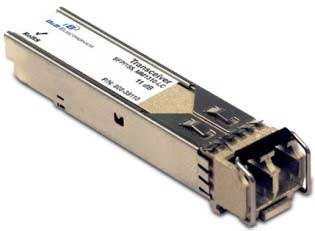
Figure 1: SFP Transceiver
Active Thermal Cooling
An active thermal solution that requires no maintenance and can cool hot spots below surrounding ambient conditions is thermoelectric or Peltier coolers. This is a semiconductor-based device made from Bismuth Telluride that has unique properties to pass through electric current while causing high thermal insulating characteristics. As a result, a small heat pump is formed that removes heat from the control side to the hot side. Ceramic substrates are used for heat spreading and electrical isolation to pass thru current on each P and N junction element. A Peltier cooler can be as small as 2 x 2 mm’s, allowing it to operate in tight space constraints. Below is a schematic of a thermoelectric cooler.
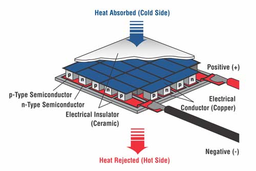
Figure 2: Schematic of a thermoelectric cooler module.
Laird Thermal Systems has developed a unique thermal solution using Peltier coolers for optical transceivers. The key challenges were:
- Maintaining a high Coefficient of Performance (COP) to limit heat rejection requirements from thermoelectric coolers onto natural convective heat sink.
- Durable construction to operate in elevated temperature environments, up to 120°C.
- Develop a thermal solution with a high degree of reliability.
The objective was to design a thermoelectric cooler assembly that can remove heat generated by optical transceivers running in environments where temperatures can exceed 95°C.
Active Transceiver Cooler (ATC) Assembly
Laird Thermal Systems’ active cooling solution optimized the performance and efficiency by developing a custom thermoelectric cooler assembly, see figure 3. Customization down to the TE element allows for optimization of heat pumping capacity to heat rejection mechanism for operating conditions with a ΔT of roughly ~30°C. The thermoelectric assembly is designed to accommodate specific footprints and input power constraints commonly available in the optical component market. Our Active Transceiver Cooler (ATC) line of miniature form factor Peltier units are designed to work with optical transceivers.
The thermoelectric cooler uses a high temperature solder construction. It is designed to accommodate the footprint of an EMI cage that goes around the optical transceiver. Our interface materials are used to mount onto mating heat transfer surfaces and clips are used to assemble the ATC Cooler onto the EMI cage. An aluminum plate is used for structural integrity of the assembly and to aid in heat spreading. An NTC thermistor is adhered to the control side for temperature control.
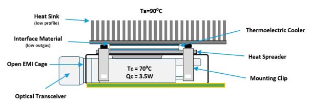
Figure 3: Active Transceiver Cooler (ATC) assembled to an EMI Cage.
Closed versus Open cage design
The problem with the closed cage type of ATC cooler is that it leaves a 1 to 2 mm air gap between the EMI cage and the optical transceiver, causing an insulating barrier. Customer test results show a large temperature differential across the air gap of 14⁰C. To make sure the transceiver does not exceed its maximum operating temperature limit of 70ºC, the thermoelectric cooler needs to maintain a temperature below 40⁰C.
To improve performance, Laird Thermal Systems has designed the open cage ATC Cooler. By using an optimized heat spreader and an open EMI cage, the thermal resistance of the control side can be reduced, making the Peltier Cooler work more efficiently.
To validate the improved performance of an open cage ATC Cooler, we simulated a test setup, as shown in Figure 4. This allowed us to test the system design under various conditions dependent on the heat load generated for a typical QSFP transceiver. Test results in figure 5 proves that the open cage ATC has higher Qc power than the closed cage ATC.
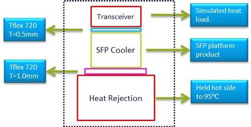
Figure 4: Test setup of Closed versus Open cage ATC Cooler.
| ATC Closed Cage | ATC Open Cage | |
| Qc max | 18 W | 22 W (22%) |
| ΔT max | 59⁰C | 61⁰C |
| COP | 1.2 | 1.5 (25%) |
| Normal Current | 3.0 A | 3.0 A |
| Normal Voltage | 5.0 VDC | 5.0 VDC |
| Input Power | 15 W | 15 W |
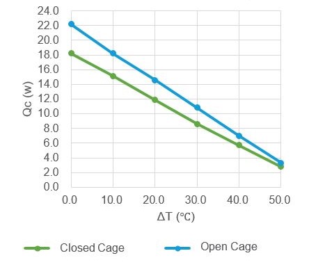
Figure 5: Performance Comparison ATC Open Cage versus Closed Cage. Th = 95⁰C, V = 5 VDC, no load
Conclusion
In an outdoor environment, the open cage Active Transceiver cooler (ATC) yields an optimal solution to maintain form factor and minimize latency of a remote radio unit. With almost no maintenance or operating costs, thermoelectrics are ideal for keeping optical transceivers below their maximum operating temperature. Laird Thermal Systems’ Active Transceiver Cooler provides a compact form factor and the cooling efficiency needed to maintain peak performance of QSFPs under ever increasing data transmission speeds for next generation 5G networks.