Introduction
The history of thin film semiconductor manufacturing has been one of constant process improvement. This constant process improvement was necessary in order to establish cost effective high yielding production lines as they struggled to keep pace with Moore’s law. All of this has been made possible through the integration of automated metrology systems with statistical process control.
Today, automated metrology systems are implemented throughout the manufacturing process. Some of the key parameters measured are thickness, refractive index, resistivity and stress of the thin films. These systems are used to not only characterize all of the physical properties of the device during fabrication including: the electrical, optical and mechanical properties of the material but to feed this information back into the manufacturing process.
Since many of the properties of a thin film are also temperature dependent, temperature stability is key and thermal management is critical. In addition, temperature control of the stages and other critical components are required for accurate and repeatable measurements over lengthy periods of time.
In this application note we will review two major thermal management systems that are in use and the emerging trends for metrology systems and the implications for their associated thermal management systems.
Metrology Trends
Metrology strategies usually differ according to the number and type of integrated circuit. Metrology tools that work within one process tend to be more stable. Those that are applied to differing products will require periodic requalification. One example of an evolution in metrology can be found in the measurement of the thickness of a thin film. Various thin film measurement methods, such as surface profilometry and resistivity measurements are very difficult to carry out during processing, and analysis of thin film growth rate is usually performed after the deposition run. Traditionally elipsometry was used for thin film thickness measurements but it lacks the ability to make measurements when the film is opaque. In this area ultrasonics are especially valuable for measuring the thickness of various films.
Though the tooling and strategies may change some things remain constant. The number of measurement points varies according to the semiconductor device manufacturer and/or device.Metrology is undertaken according to the following sampling method: 10 to 100 points for one die with 5 to 20 die taken from one wafer and 1 to 2 wafers taken from each lot (25 wafers). Newly designed devices may go through several thousand metrological processes for one wafer during the start-up period of manufacture.
Metrology Implemented for Process Control
Traditionally metrology is the measurement of physical dimensions such as length, thickness, diameter, taper, angle, flatness or wafer bow, but it may also include electrical resistivity, optical reflectance of the thin film etc. Any parameters that play a role in the behavior of the thin film need to be characterized and tracked through the manufacturing process.
One major change in the semiconductor industry has been the introduction and use of real time process control. Here sensors are used to provide live feedback of local process conditions to the process tool. This data can be used to modify the process parameters of the tool or to stop the line. This type of test characterization is referred to as in-situ process measurements.
These measurements are not repeated after the device is finished and instead electrical function and parametric behavior of the device are revealed under test. This post fabrication test may also be repeated during or after stressing the part.
The table in the pdf version of this application note provides examples of points in the fabrication process where measurements of key parameters are made. This table was taken from the Handbook of Thin Film Deposition Processes and Techniques: Principles, Methods, Equipment and Applications, Second Edition, Chapter 6 The Role of Metrology and Inspection in the Semiconductor Fabrication Process by Mark Keefer, Rebecca Pinto, Cheri Dennison, and James Turlo.
The need for higher throughput, higher packaging density and repeatability combined with a high speed optical or electrical measurement system places ever increasing demands on the thermal management system associated with each metrology tool. Furthermore, the lack of good temperature control will lead to bad data, incorrect decisions, conclusions and significant yield loss. One such system is shown below.
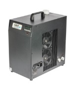
MRC-300 Chiller
Cooling Methods
Direct Cooling
Stages upon which the semiconductor wafers are placed for measurement can be temperature controlled using a thermoelectric cooler assembly. Thermoelectric cooler assemblies can be used for precise temperature control as they can change the heat pumping direction through the device under test by reversing the current flow through the device. This allows the thermoelectric cooler assembly to be program controlled very precisely. Temperature stability to within ±0.01°C is achievable under steady state conditions. For this type of cooling application thermoelectric cooler assemblies from tens of watts to more than 300 Watts of cooling capacity are required.
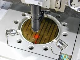
An optical inspection tool for a semiconductor wafer
Liquid Cooling
The water-cooled stainless steel measurement stage can also be cooled using a water-glycol mixture. The channeled cold plate is directly attached to the measurement stage and a chiller provides a cooling fluid to maintain precise temperature control. Usually highly reliable thermoelectric based chillers with 150W and 300W capacity are used to provide this capacity. Units such as these are designed for bench-top or rack mount configurations.
Critical Components
- Pump: High reliability, long life and low noise are some of the key factors in selecting a pump for semiconductor applications. Leak proof is another key feature.
- Thermoelectric Coolers: Need to have high heat flux density, provide cycling reliability for heating mode and long life continuous operation.
- Heat Exchangers: Compact, low thermal resistance air heat sinks and liquid heat exchangers are required for optimal heat dissipation and absorption.
- Fans: High reliability with sufficient airflow at high static pressures, 24/7 continuous operation for minimum five years. High MTBF with low noise and high CFM are ideal for semiconductor application.
- Temperature Controller: Provides accuracy and stability of temperature over time. The controller should be user-friendly and easy to integrate with end user software. Maintain secure continuous communication with metrology tool without any loss in connection.
Case Study
A semiconductor tool manufacturer in Silicon Valley had a need to develop a wafer defects and surface flatness measurement tool for semiconductor chip manufacturers. The requirement was to provide a liquid cooling system for stage as well as stage control motor with precise temperature stability. The key requirement is reliability of system with minimal down time under 24/7 operation and stability of temperature control to as tight a tolerance as possible. The requirements were to remove up to 75 Watts of heat and hold temperature steady at 25°C. The system impedance of coolant circuit was 14 PSI with flow rate requirement of 4 lpm.
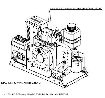
Before proceeding the four primary components of the system were reviewed including: 1) Pump, 2) PSU, 3) Relay and 4 Fan. Each of them were evaluated for reliability. Along with these active components interconnects were evaluated for adherence to design specifications including the tubing as shown below.
Changes Investigated
Tubing Wall Thickness
In 2005, a change was initiated to use thicker-walled tubing for two of the tubes in the system; at the inlet and outlet of the pump. The purpose was to investigate if this implementation would be beneficial for all tubes in the system.
Tubing Length
The tubing lengths and routings had not been reviewed after the new pump was incorporated. Each tube was analyzed individually to determine if the length specified was correct for the designated route.
Tubing Material
Alternative plastics, reinforced tubing and molded tubing were also explored. Several flexible tubing materials were investigated for kinking under both soft and harsh bends including the PVC that is currently in the system, Tygon, polyester reinforced PVC, and wire reinforced PVC.
Most of the materials investigated had similar bending properties, and are expected to remain kink-free with the soft bends at the proper tubing lengths. One material, the wire reinforced PVC, is intended for both positive and negative pressures and is both kink and crush resistant.
The critical component in this system is not surprisingly the pump. Below is a description of the test conditions used to evaluate the pumps under consideration.
Test Procedure
Low Level Condition Test
The purpose of this test was to check that the pump would restart after the pump had been shut-off due to a low water level alarm.
- Relay was added to the pump circuit, and the unit ran overnight.
- After 21 hours of operation, the reservoir was opened and the float was pressed down. When the float was pressed down, the pump would stop and the Low-Level light would illuminate.
- Different durations for holding down the float were tested.
| Duration | Result |
| 1 second | Pump restarted |
| 5 seconds | Pump restarted |
| 20 seconds | Pump restarted |
| < 1 sec (quick tap on float) | Pump stayed off |
Power Interruption Test
The purpose of this test was to confirm that the pump would restart after a brief loss in power.
- After the low level test, the unit was restarted.
- After approx. 70 hours of operation, the on/off switch was toggled as rapidly as possible.
- Result: The pump stopped; and restarted approximately one second after power was restored.
- Power inlet plug was loosened from the wall, and power was removed and restored as quickly as possible.
- Result: Pump stopped, then came back on approximately one second after
The addition of the pump relay is expected to eliminate stoppage in both of the real-life situations tested, Power Interruption and Low-Level Alarm condition. Previous testing on the pump circuit with the DPDT relay has shown that the time for discharge is less than 0.5 seconds. A slight delay in the output of the power supply after initial power up (~ 1 sec) allows the pump enough time to discharge and then restart. The only condition resulting in a failure was a very quick tap on the float sensor. This is not expected to occur under normal operation.
Challenges
There were several challenges associated with developing a recirculating chiller with precise temperature stabilization, the most challenging are listed below. To follow up on this we will identify some of the errors introduced and briefly discuss its solutions.
Temperature Stabilization: The temperature control is within the range of ±0.02°C with the set point maintained continuously.
Temperature Accuracy: The temperature needed to be within ±0.02°C. Erratic behavior can occur with off-the-shelf controller, ref Figures 1-4.
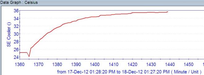
The figures below show some of the issues found with the temperature controller. In Figure 1 we can see that there has been some fluctuation in the temperature. This may have resulted from a change in the thermal load or incorrect PID settings.
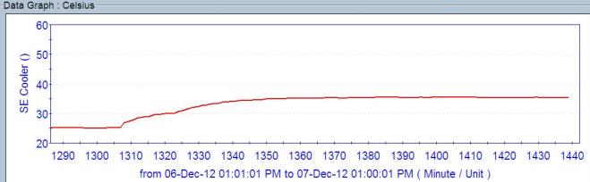
When the chiller fails it will not reach set point temperature and a gradual increase in the temperature may occur. In figure 2 the chiller shows insufficient cooling capacity, which may result from exposure to a high ambient environment, increased thermal load or insufficient coolant pumping.
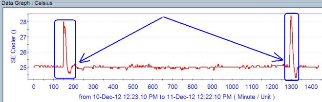
In figure 3, the temperature shows erratic behavior either due to a change in the temperature ambient, instantaneous change in the thermal load or lost connection to the temperature sensor.
In figure 4, the set point temperature was not reached and thermal run away occurred. This was due to high ambient conditions and higher heat loads than chiller was designed to handle. Sometimes this can also occur from firmware glitch caused by bad temperature sensor and firmware.
- Coolant: To maintain water quality, special filters and inhibitors were tested to maintain the best coolant quality over extended periods of time.
- Copy Exact: This has been a standard in the semiconductor industry, as all tools are required to conform to identical design specifications. This allows for no deviation or customization.
- Reliability: The system is expected to run 24/7 due to demand from the front-end semiconductor fabrication industry. Special and detailed attention is required for component selection.
- After Sales Service: Extended warranty and special after sales services are usual and customary for the industry. Extensive sales staff training is required to enable quick turnaround and problem solving for end users.
- PID Controller: To improve temperature stability and accuracy a custom PID controller was developed that interfaces with the tool manufacturers’ system software and provides alarm features for maintenance and failure.
Summary
Laird Thermal Systems developed a new set of design criteria for a design of experiment (DOE) described above. The parameters were derived through rigorous testing; subsequent experiments allowed us to better define a new set of specifications for the components. While it may have increased the underlying cost we sourced new components based on these specifications. As a result, we were able to develop a robust thermoelectric recirculating chiller with 300 Watts of cooling capacity.
The critical component in the chiller was not surprisingly the pump. This was sourced from a high reliability component supplier with a unique bearing technology. This pump had special ceramic bearings that minimized friction and wear. This resulted in high mean time between failures (MTBF). The pump was also modified for a small form factor to fit within the current physical constraints.
The second critical component was the controller. A custom controller was developed with optimized preset PID settings. The Software was designed and integrated into the customer’s system to match accuracy and stability based on customer’s environment, heat load, cooling circuit and pressure. A GUI with custom alarm features was used to identify low and high temperature level alarms and low fluid level alarms. The controller was also designed with a tamper proof feature to limit a technician’s ability to change setting parameters.
We also looked to the industry to see which devices had been improved since the time of the original design. As a result, new high-performance fans with MTBF of 62K hours were incorporated into the assembly. With these new higher reliability mechanical components we were able to extend the lifetime of the device.
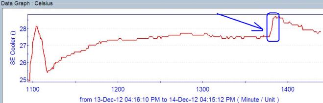
The result of the changes described above produced remarkable results for both temperature control and extended life as shown in Figure 5. This graph shows the final stability of the system with removal of all previous temperature control issues from the standard controller. In the end we were able to achieve significantly improved temperature stabilization with improved temperature accuracy.
