Introduction
Cooling and temperature control systems are used throughout semiconductor fabrication facilities. In fabrication facilities both large and small, hundreds to thousands of cooling systems are installed and operate continuously. The processes employed are usually setup as copy-exact, which means the process systems are developed and transferred from the OEM of the process tool. These critical production tools used in semiconductor fabrication facilities are required to be reliable and easy to service to deliver minimum downtime. The same is required of the cooling systems that support them. Usually the cooling systems employed have a water-cooled evaporator instead of an air-cooled evaporator. A liquid-liquid unit is quieter than a liquid to air unit because a fan is not required. Even more important, the heat can be rejected by available general facility cooling water and the heat is not rejected into the air temperature conditioned environment. These cooling systems can be placed near the tool, hidden in a false floor or on the lower level in a sub-floor. Cooling systems are built to meet SEMI S2 or F47 standards. OEM customers vary in their demand according to their unique requirements, but compliance is mandatory and sometimes OEM customers ask to get certifications for SEMI S2 or F47, which includes for example seismic “protections.” In these fabrication facilities a variety of liquid cooling systems are used including: compressor and thermoelectric based recirculating chillers.
Cooling Systems
Liquid cooling systems are required to:
- Protect the tool process against chemical reaction by avoiding an unknown Wetted-Parts- Material-Mix
- Achieve a stable temperature, independent from facility water temperatures that can change
- Achieve a temperature below or above the facility water temperature
- Solve different temperature or fluid requirements at one tool with a multi-loop liquid cooling system
In semiconductor fabrication facilities, the required temperature control range varies from -80°C to +150°C. For the majority of applications, only one stable temperature set point is required. In the final chip test environment however, temperatures are required to vary in order to stress the chip. Here different temperature set points need to be reached with a single thermal management system. Due to the high-precision processes, tool manufacturers demand a very stable temperature environment. Typical of these requirements are +/-0.1K stability (e.g. for etching) to ±0.001K (e.g. for lithography) while cooling capacities can be up to several kilowatts.
In semiconductor fabrication facilities, custom multistage compressor based chillers are used to support cooling for very low temperature requirements. Most standard chillers utilized need some form of modification to meet semiconductor process facility requirements and may even require a water-cooled condenser. Some of the installation base also uses thermoelectric (19” rack) cooling systems, i.e. for etch applications, instead of compressor-based systems.
The cooling capacity demands and the range over which the system operates varies from a couple of hundred Watts (thermoelectric chiller and compressor based systems) to hundreds of Kilowatts (liquid-to-liquid cooling systems). The majority of the installed base uses liquid-to-liquid cooling systems that operate close to ambient and are based on a fluid-to-fluid heat-exchange principle.
The cooling systems utilize facility water to prevent heat dissipation of the cooling unit from warming the cleanroom and destabilizing the process tool’s thermal management system. These liquid-to-liquid systems keep the air quality level high by avoiding dust up introduced from the airflow of an air-to-air thermal management system. This consideration is independent of the location of the thermal management system. Due to the cyclic nature of the market, product requirements change and time to market is crucial. The cooling system solution developed is usually a custom product with a unique approach and design specific to the OEM.
Technical Requirements
Cooling systems are often placed in the sub-fab, which means they are located one or two floors below the tool they are connected to. For cooling systems that use water as coolant, the height between the tool and the cooling system cannot exceed 10 meters, otherwise the height difference can cause the water to boil as the pressure is lower than the vapor pressure of water.
If the cooling system is placed at a lower level, the coolant circuit can function as a closed loop to the atmosphere. In this case, the cooling unit needs to incorporate a closed pressurized reservoir (7 PSI pressure cap) to minimize over flow conditions. The reservoir can be designed as a flow through reservoir or as a standpipe reservoir with a pressurized cap.
Flow-through reservoir
Standpipe reservoir
A standpipe reservoir introduces additional fluid to the liquid circuit as required, whereas a flow-through reservoir continuously exchange fluid. It is important to know that the pump simply needs to overcome the height and pressure difference one-time during start-up in a closed loop system, as the supply and return lines will equilibrate given that they have the same length and diameter.
Material Compatibility
In the semiconductor process environment, copper and brass are materials with limited compatibility due to their susceptibility to galvanic corrosion. Wetted parts, which come in direct contact with the medium (liquid), are typically made of stainless steel. These parts range from the complete plumbing circuit of the cooling unit to the process loop. Stainless steel is usually used in the process loop due its resistance to galvanic corrosion or because a special fluid is used that is not compatible with PVC, copper, and brass etc. When stainless steel is required, the heat exchanger, valves and the pumps will require special consideration. Occasionally, stainless steel may require additional passivation or a limited subset of stainless steel materials may be used.
If copper or brass is used to accommodate cost considerations, the material needs to be insulated to minimize the thermal impact on the system from outside thermal sources. Special particle free insulation may be required in this instance.
Special fluids used in the semiconductor environment include: di-electric fluids (Galden, 3M Novec), which are non-conductive. Special hoses and sealings need to be used for these fluids and special attention to handling is also required. These coolants run in a closed loop as the fluid vapor pressure is relatively low compared to water.
The use of de-ionized water is common. Copper or brass can be run up to 3 MOhm-cm resistivity if the set point temperature does not exceed 30°C for extended periods of time. However, to ensure long lifetimes and for higher resistivity demands, the cooling system should be equipped with a nickel brazed or complete passivated stainless-steel evaporator/heat-exchanger. The pumps should be stainless steel and all component parts in contact with the fluid should be made of passivated stainless steel to prevent corrosion. This is referred to as high-purity plumbing. In addition, a DI cartridge can be equipped with an indicator light or regulated through the cooling system and the DI level will be constantly measured and monitored keeping to a preset resistivity. The DI cartridge filters the ions out of the fluid and needs to be replaced to ensure its effectiveness.
Valves
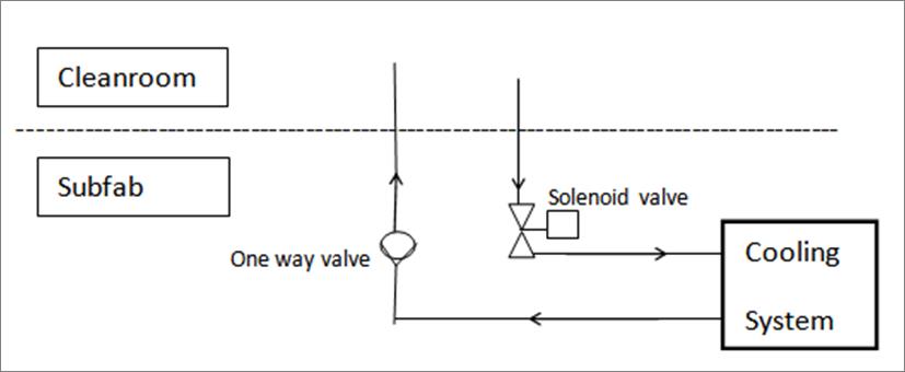
If the unit is placed below the fabrication floor, an anti-siphoning package can be used to avoid backflow of the fluid and prevent overflowing the unit in event the pump stops. The anti-siphoning package consists of a one-way check valve in the supply line and normally open solenoid valves triggered by the unit in the return line. The solenoid valve would close in case the pump stops and the one-way check valve allows for the flow in only one direction. Instead of a one-way check valve, another solenoid valve can be used, though this depends on the flow rate and size.
For a process facility, constant monitoring and control of the facility process water is required and modulating solenoid valves from Siemens or Bellimo need to be used. The valve diameter and actuating motor have to be sized correctly to achieve stable temperatures and trigger the correct switching cycles. Assuring this means the inclusion of a long-lasting actuator and facility water flowing through an acceptable pressure drop from the facility water supply and return. Sometimes three-way mixing valves are used. This allows for continuous flow into the facility water loop and adds cooling for the heat exchanger of the thermal management system when required. The constant flow back to the facility water loop avoids a water hammer in cases where it would close and reopen when cooling is required. Flow requirements can be as high as hundreds of liters per minute.
Space Consideration
Cleanroom costs can be up to $60,000 /m2, therefore the chiller footprint is important and can have a costly impact. Semiconductor cooling systems should be stackable (stacked high) and preferable narrow to maximize space and minimize their impact on costs. Therefore, the design of a cooling system’s footprint needs to be closely examined. The system should also be located where it is easy to access from two sides. Routine maintenance on cooling systems is required to exchange components such as pumps, motors, valves and fans to maximize system uptime.
Semi Requirements
For a completed tool, OEMs require a SEMI S2 certification and sometimes a Semi F-47 certification in areas with high earthquake probability. As the SEMI S2 certification requires a high amount of documentation, subsystems like a cooling unit will finally be integrated into the tool. Most of the time it is sufficient to meet the intent of Semi-S2 and the OEM will do a full certification of the final tool with all incorporated subsystems in their NRTL laboratory. Below are some items to consider when designing a cooling unit to meet Semi-S2 and F-47 standards.
SEMI S2:
- Drip tray must be large enough to hold 110% of the volume of the largest container in the cooling product
- EMO button and/or EMO connection
- Seismic brackets, seismic tie downs for standalone units
- A specific power connection setup depending on the power consumption
F-47:
- Continue to run during a power drop for a given time and fixed reduction of power
These requirements vary from customer to customer, but to some extent the certification is known to the manufacturer of the system.
If the unit is not placed below the fabrication facility flooring, the cooling system will instead be placed in the cleanroom or a grey room. Again, requirements here can vary drastically from customer to customer. If the cooling system, sub-assembly or any component is required to be in the cleanroom, then the entire assembly including each component must be as clean as possible. This requires the entire manufacturing process to have a high level of attention to cleanliness. Debris, dust, burrs or chips occurring at every process step need to be examined and removed ideally after every fabrication step. The industry is quite sensitive to this.
After the final assembly, the cooling unit needs to go through a manual check with UV-light and wipe down for final cleaning with gloves. The unit is then double bagged and each bag needs to be labeled appropriately. There are suppliers who specialize in cleaning, to semiconductor standards, and this can be subcontracted. Since it contributes to the cost and lead-time, the level of detail used requires scrutiny.
Service
Selling a cooling unit into the semiconductor market requires long-term servicing agreements in the contract. If a product is qualified in one facility, other facilities can take over the setup as a copy exact requirement and use the existing cooling solution. For this after-market service and support, full understanding of the end users demands is critical. Service and support needs to responsive. In the event a tool unexpectedly goes down, immediate support is required or the OEM can lose millions of dollars in revenue.
Once the tool is installed service needs to be done on-site on the same day of failure, as large cooling systems cannot be replaced easily or shipped back to manufacturer for repair. OEMs have moved away from purchasing redundant cooling systems as their processes are getting leaner and expenses are reviewed more closely. This puts the contractual emphasis on service and a global service infrastructure.
Ideally the manufacturer is aware of the service demands and support strategy of their customers. Systems today are designed to minimize the downtime and make use of hot swappable parts, such as pumps on rails or modular exchange of complete assemblies, including electrical control boxes.
Conclusion
A semiconductor fabrication facility’s unique environment makes designing and building a liquid based cooling system one of the most challenging environments. Careful consideration is required not only for component selection, but also on the overall liquid cooling system unit and its integration with a semiconductor tool. Challenges designers face include the type of heat transfer mechanism utilized on the control and heat dissipation sides, material compatibility, valve control, cleanliness, space optimization, semi compliance and serviceability. These are all areas in need of attention to detail to properly ensure an optimized total cost of ownership.